The Feast

Bengi Ada Tüfekci

Alpha Masking

Validation of Correctness

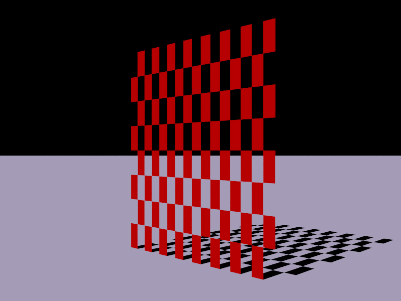
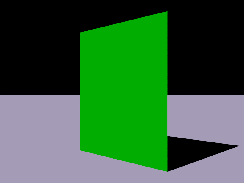
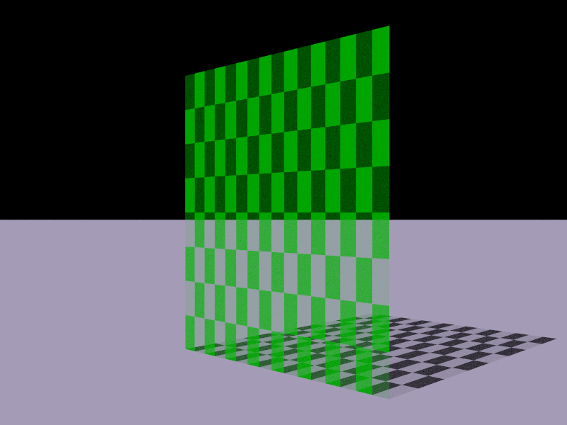
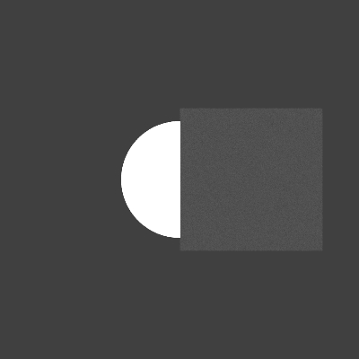
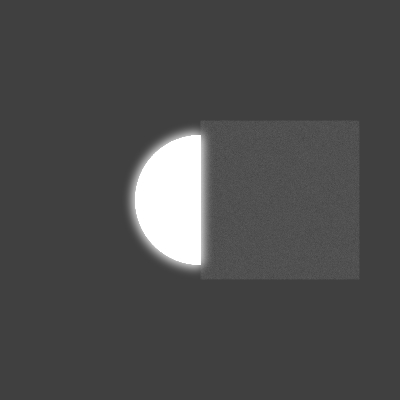
I validated the correctness of my implementation by rendering objects with alpha masking enabled and verifying that regions behind the masked areas remained visible. I also checked whether the resulting shadows matched the expected behavior.
I used a checkerboard alpha texture to test my implementation. For fully opaque and fully transparent regions, the visibility and shadowing were as I expected, as it can be seen above. I also tested partial alpha masking with a semi-transparent checkerboard pattern in both dark and light regions. The shadows from the darker areas were lighter than with a fully opaque cells, and the shadows from the lighter areas were slightly darker than those of the fully transparent cells, which is what I expected. This test can be seen below.

Implementation

Files Modified

  • include/lightwave/instance.hpp - I added an optional alpha texture to the Instance class.
  • src/core/instance.cpp - In Instance class's intersect function, I implemented alpha masking by randomly rejecting surface intersections based on the mean value of the alpha texture evaluated at the surface UV coordinates.

Biggest Challenge

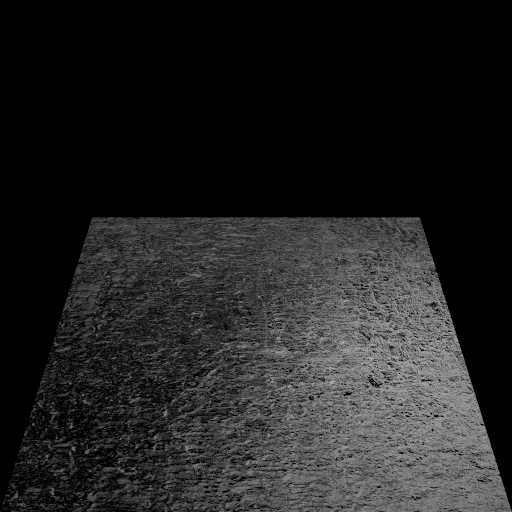
I encountered a time-consuming bug where, for regions with alpha masking, intersections both before and after the masked region were also incorrectly treated as masked. This caused those pixels to be rendered black. This was caused by me forgetting to revert the intersections variable to its previous state when an intersection was rejected due to alpha masking.

Note: My implementations is not intended to work with shapes with alpha masked regions that intersect - for examples with spheres, as I only required alpha masking for meshes and rectangles. For that, intersections after an alpha masked points should also need to be considered.

Area Lights

Validation of Correctness

I validated the correctness of my implementation by rendering the same scenes with area lights in both Mitsuba 3 and my renderer and comparing their outputs.

I also compared a scene using area lights with an equivalent scene using only emissive objects. Using area lights led to slightly less noise.

Implementation

Files Modified

  • src/lights/area.cpp - I added a new AreaLight class implementing the sampleDirect function. It contains: a reference to a shape, area light's power, and an optional transform. The sampleDirect function:
    1. Samples a point on the shape
    2. Transforms the sampled point into world coordinates if a transform is present
    3. Constructs a vector from the shading point to the sampled point
    4. Computes the weight by multiplying the cosine of the angle between the outgoing direction and the surface normal with the light's power, and dividing by the squared distance and the sampling PDF
  • src/shapes/sphere.cpp - I implemented the sampleArea method for the Sphere class, which samples a random point on a unit sphere and populates the sample.

Biggest Challenge

  • I created the first test scene using Blender, but each renderer used different units for area light intensity. Using the exported values directly resulted in drastically different illumination with my renderer producing extremely bright images. I was unable to find a formula to directly convert between the units, so I had to manually find the values that produced the similar results.
  • When computing the cosine term, I converted the outgoing direction vector into local coordinates. This occasionally produced NaN values for reasons I could not identify, which then caused NaN pixels in the final image. To resolve this, I had to add checks to see if there were any NaN values.

Normal Mapping

Validation of Correctness

I first compared rendering a scene using a flat normal map with rendering the same scene without any normal mapping applied. Both produced very similar results, aside from small floating point differences.

I then applied various normal maps and rendered the scene using an AOV integrator to visualize the shading normals, and verified that the resulting outputs matched my expectations for the given normal maps.

Implementation

Files Modified

  • include/lightwave/instance.hpp - I added the normal map as an optional texture to the Instance class
  • src/core/instance.cpp - I implemented normal mapping by first checking if a normal map is present after an intersection. If it is, the normal texture is evaluated at the surface UV coordinates. The resulting RGB values are first stored in a vector, then the vector is scaled and offset from the range of [0,1] to [-1,1]. Then the normalized vector is transformed to world coordinates using the surface's shading frame, and is set to be the new shading normal of the surface.

Biggest Challenge

    The biggest challenge I had was forgetting to set the linear flag to true when loading the normal textures. As a result, the normals appeared incorrect (for example, a plane with a flat and zero normal mapping texture resulted in normals completely different than the plane's original normals), which led to me spending a lot of time debugging until I figured out the problem was with how I loaded the image textures and not the normal calculation itself.
Thin Lens Camera Model

Validation of Correctness

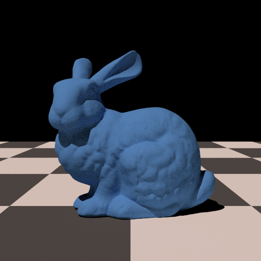
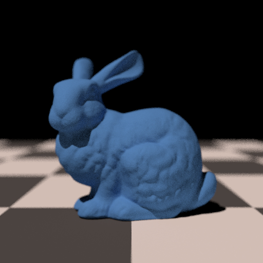
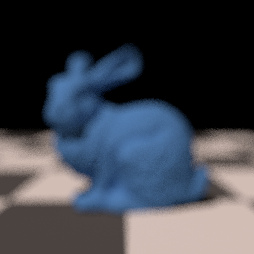
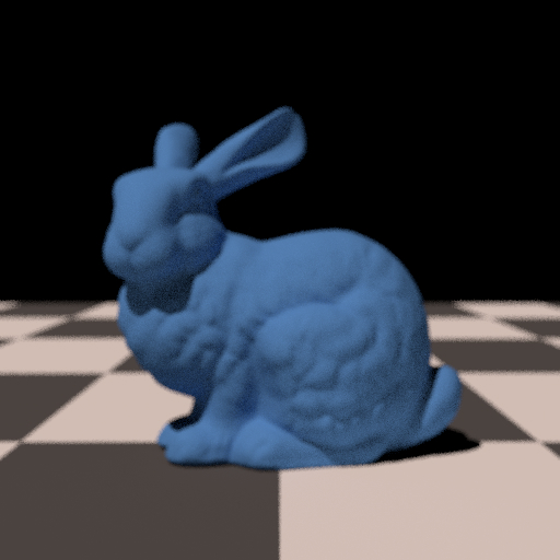
I directly followed the thin lens camera model described in PBRT: PBRT Thin Lens Camera Model . I compared renders produced by a standard perspective camera with those produced by the thin lens camera. As expected, increasing the lens radius increased blur.
By adjusting the focal distance, different parts of the scene came into focus. Objects closer to the focal distance appeared sharper, while objects farther away appeared more blurry.
Keeping the focal distance fixed while increasing the lens radius resulted in stronger depth of field effects.

Implementation

Files Modified

  • src/cameras/thinlens.cpp - I added a new Camera called ThinLens. Similar to the perspective camera, it contains Sx and Sy parameters, but also additonally includes lensRadius (which is the radius of the lens aperture) and focalDistance parameters.
  • For the sample method inherited from the Camera class: A random point is sampled on a concentric disk, which models the lens aperture. Then a ray originating from the sampled point to the focus point is constructed. Then the ray is transformed into world coordinates.

Biggest Challenge

  • My biggest engineering challenge was actually finding the lens radius and focal distances values that produced the depth of field effects I had in my mind.

Postprocessing Features

Denoising

Validation of Correctness

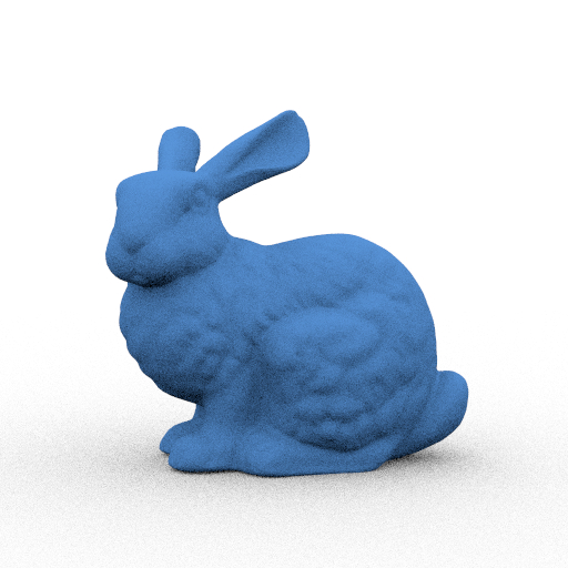
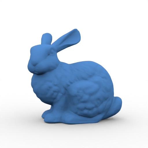
I just rendered the same scene with and without denoising and observed that the denoising did decrease the noise.

Implementation

Files Modified

  • src/postprocesses/denoising.cpp - I added a new postprocess called denoising, which implements Intel Open Image Denoise (OIDN) denoising. It takes two optional parameters, which are the AOV outputs for surface normals and albedo for denoising quality. I followed the documentation to implement the denoising filtering.
  • src/integrators/aov.cpp - I added an albedo integrator, which for every intersection, returns the albedo of the surface at that point.
  • include/lightwave/bsdf.hpp - I added a virtual method to return the albedo for a given UV coordinate.
  • For every class in src/bsdf/, I implemented the albedo method. If a material had an albedo value or texture, the corresponding color was returned at the UV coordinates. Otherwise, a constant black or white value was returned depending on the material type.
  • For this project, I only really needed the albedo of the principled material . I ultimately chose not to use the albedo texture input for denoising altogether, as I preferred the results without it.

Biggest Challenge

  • Since I used the denoising library according to its documentation, I found the implementation very straightforward.
  • I was mainly unsure what to return as albedo for certain materials (for example conductors) before choosing to return either black and white.
  • I also had some trouble actually compiling the code because of some external dependencies on my computer.

Bloom

Validation of Correctness

I validated the correctness of the bloom implementation by rendering the same scene with and without bloom. When bloom postprocessing was applied, the bright regions produced a bloom that spread into nearby regions.

Implementation

Files Modified

  • src/postprocess/bloom.cpp - I implemented the bloom postprocessing by first extracting pixels whose brightness exceeded a threshold. A Gaussian filter was then applied to the extracted image, and the resulting blurred image was added back to the original image with a user defined strength.
    The class stored the values for threshold, radius (for Gaussian), strength, sigma (for Gaussian) parameters as inputs.

Biggest Challenge

  • My biggest engineering challenge was implementing the Gaussian filter. I initially began with a full 2D implementation before remembering that separating the blur into horizontal and vertical passes was both simpler and more efficient.