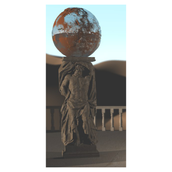
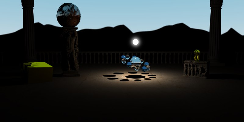
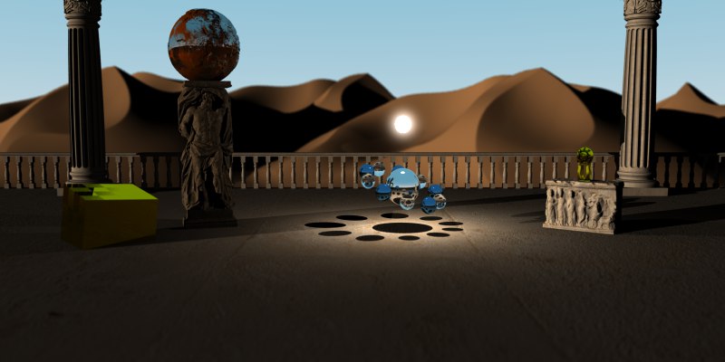
The desert of Hope
When Greek mythology meets an Egyptian ambient ...
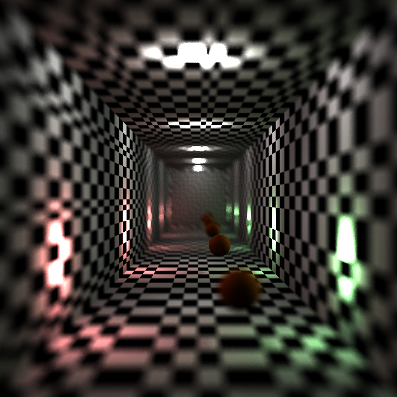
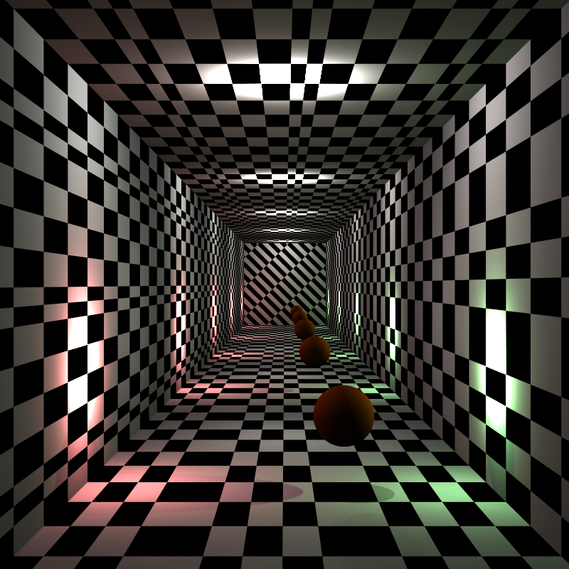
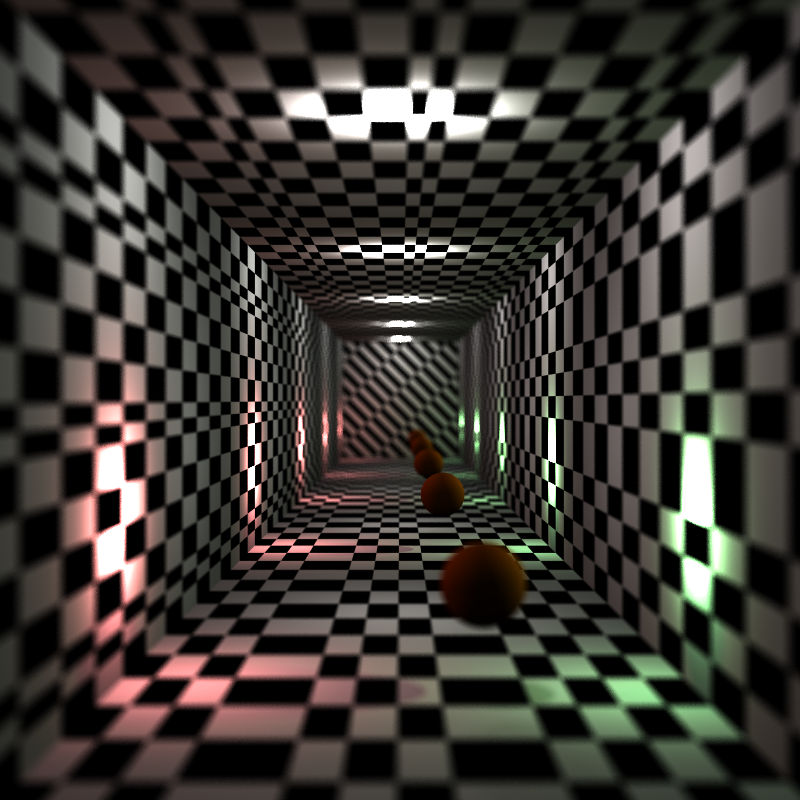
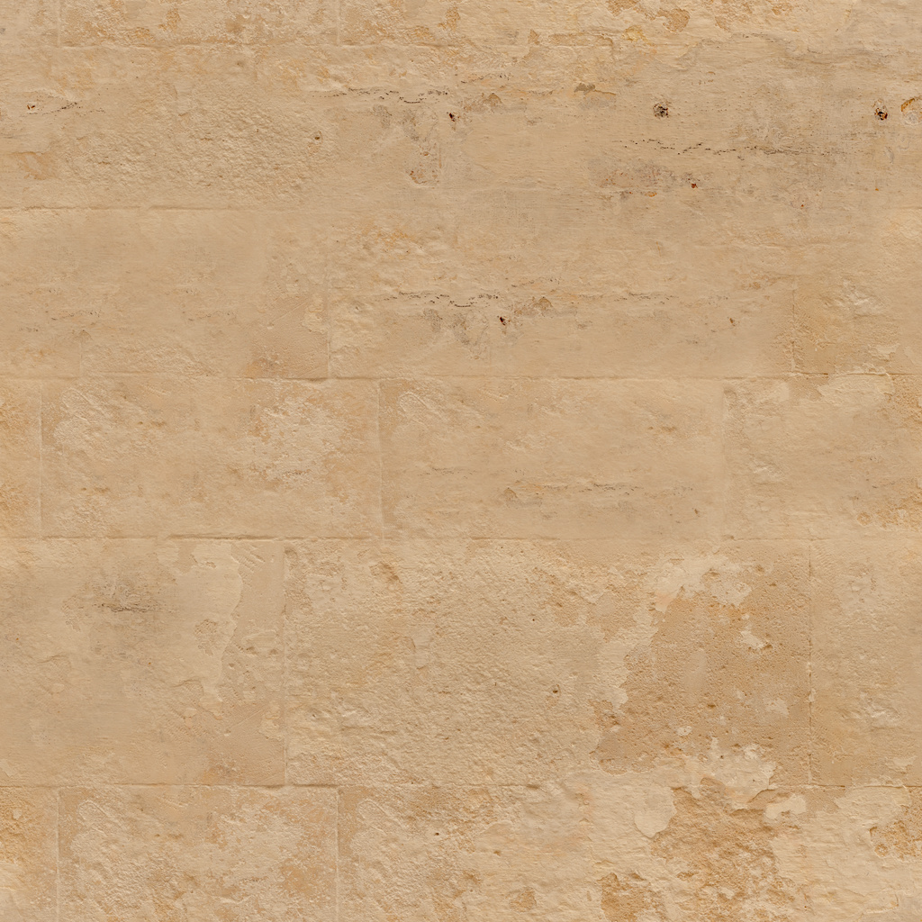
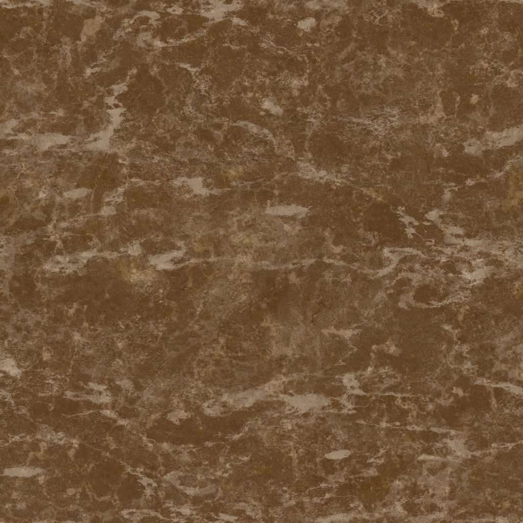
High Resolution Read More Low resolutionThe secrets of our implementation
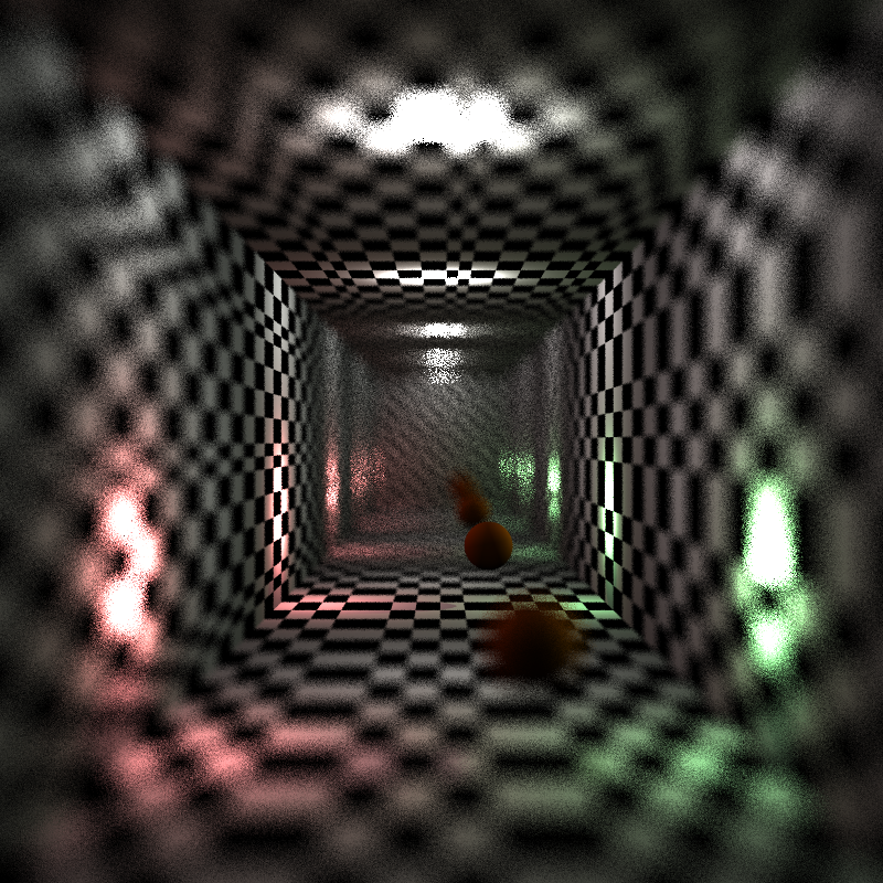
CONCEPT
It all started with the idea of a temple in the desert. We wanted to create a scene that shows interesting features but more importantly also looks amazing. On our way to our final scene we got inspired by Greek mythology as well as by the orbit of planets.
SCENE
Inspiration and Thoughts
Greek Mythology as an inspiration
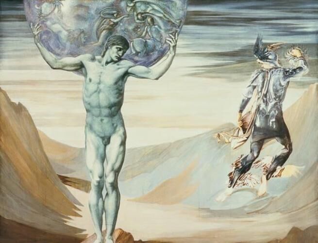
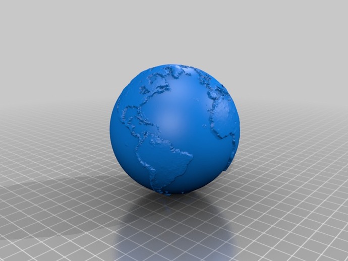
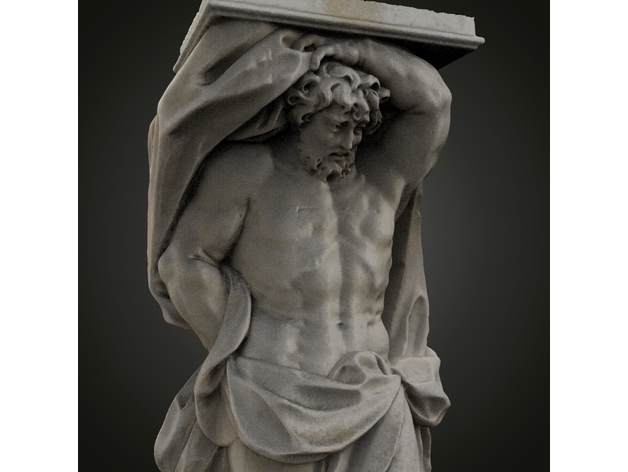
When we were looking for a nice statue that would fit our temple, we stumbled across Atlas, the titan who in Greek mythology was punished for being on the losing side with Kronos and condemned to stand at the western edge of Gaia (the Earth) and stem Uranos (the sky). We somehow really liked the image of a single person stemming the earth, because it illustrates the fragility of our planet, which has been treated as if it was indestructible. To emphasize this image, we used the rusty metal to model the globe.
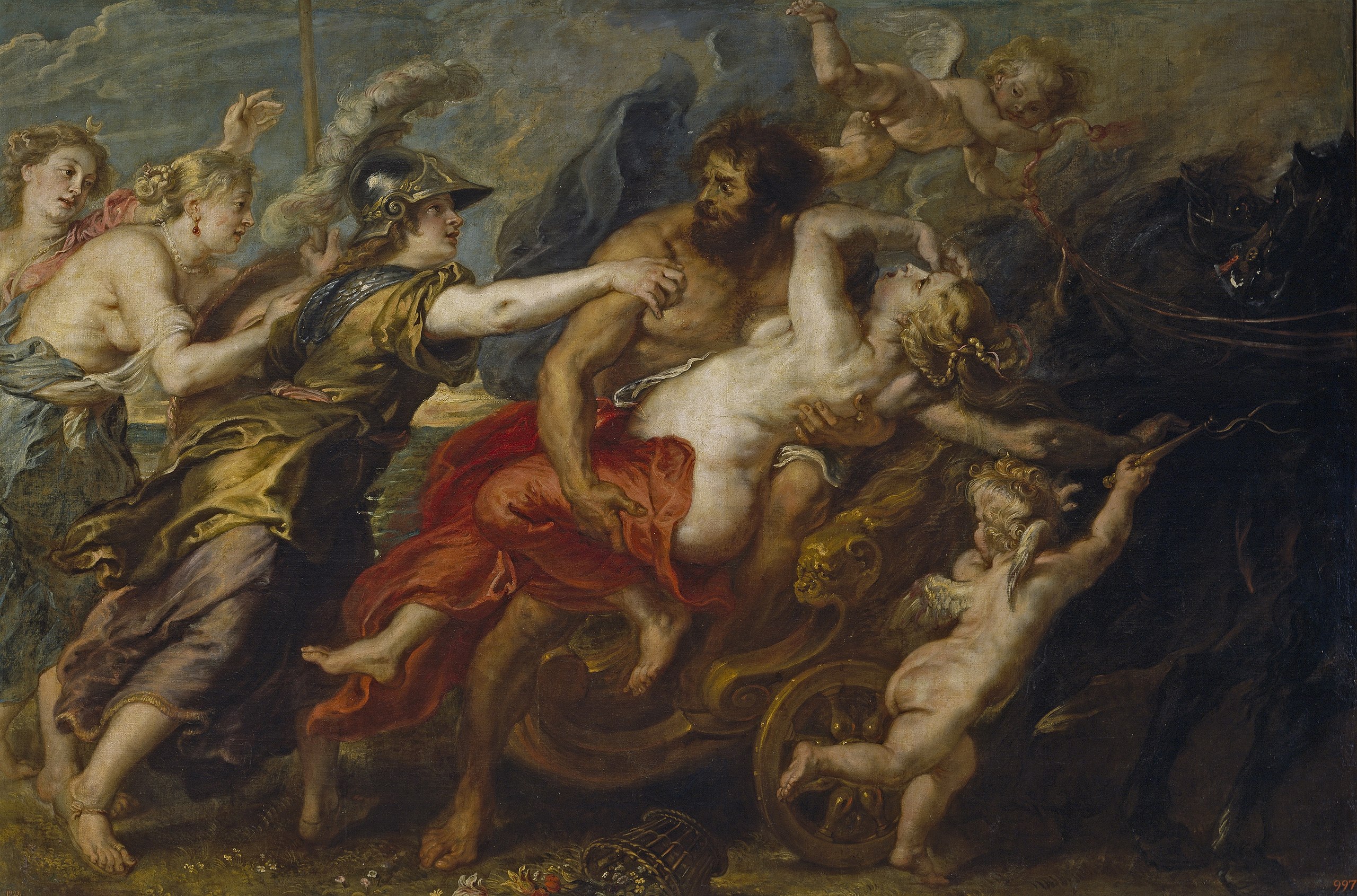
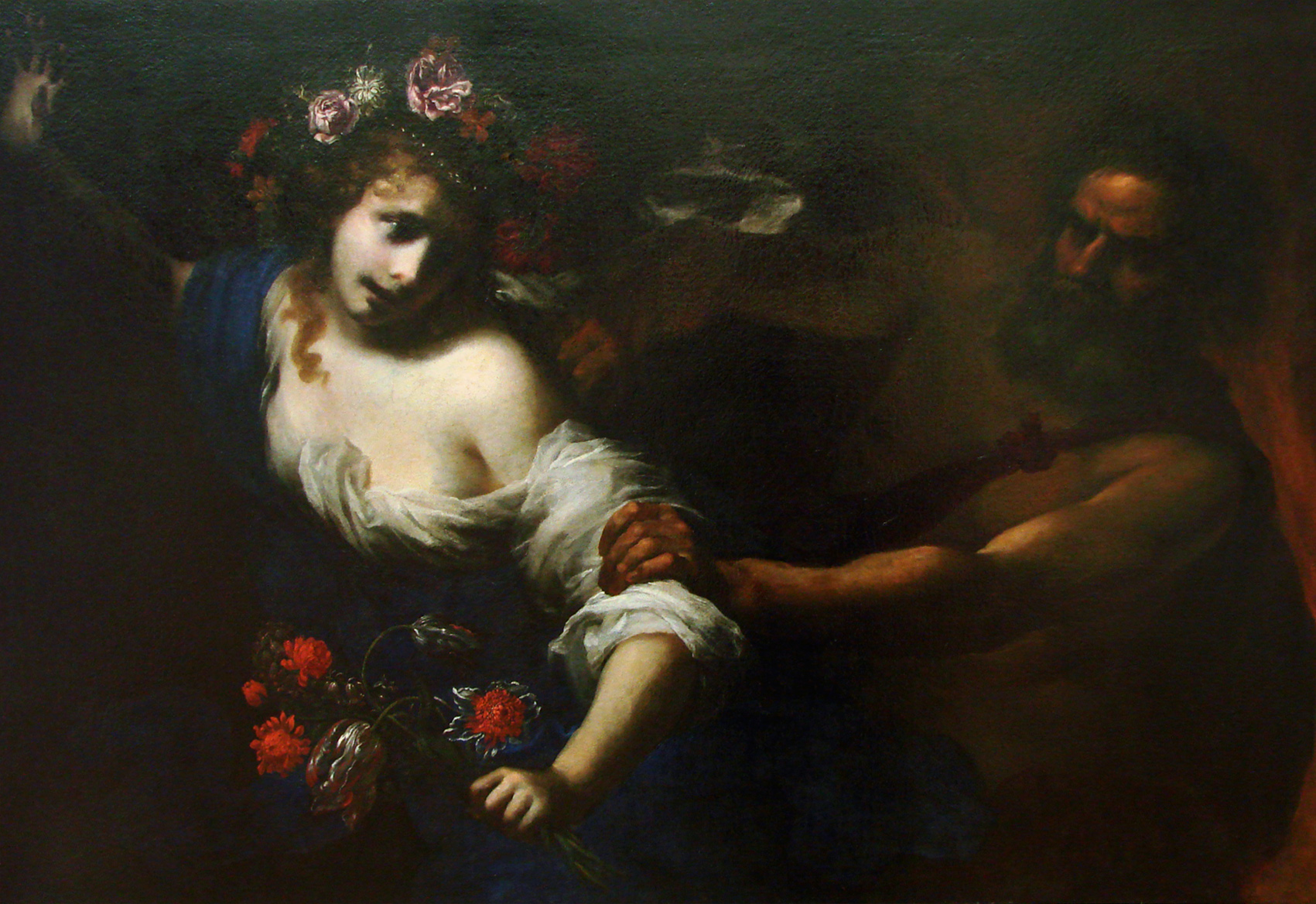
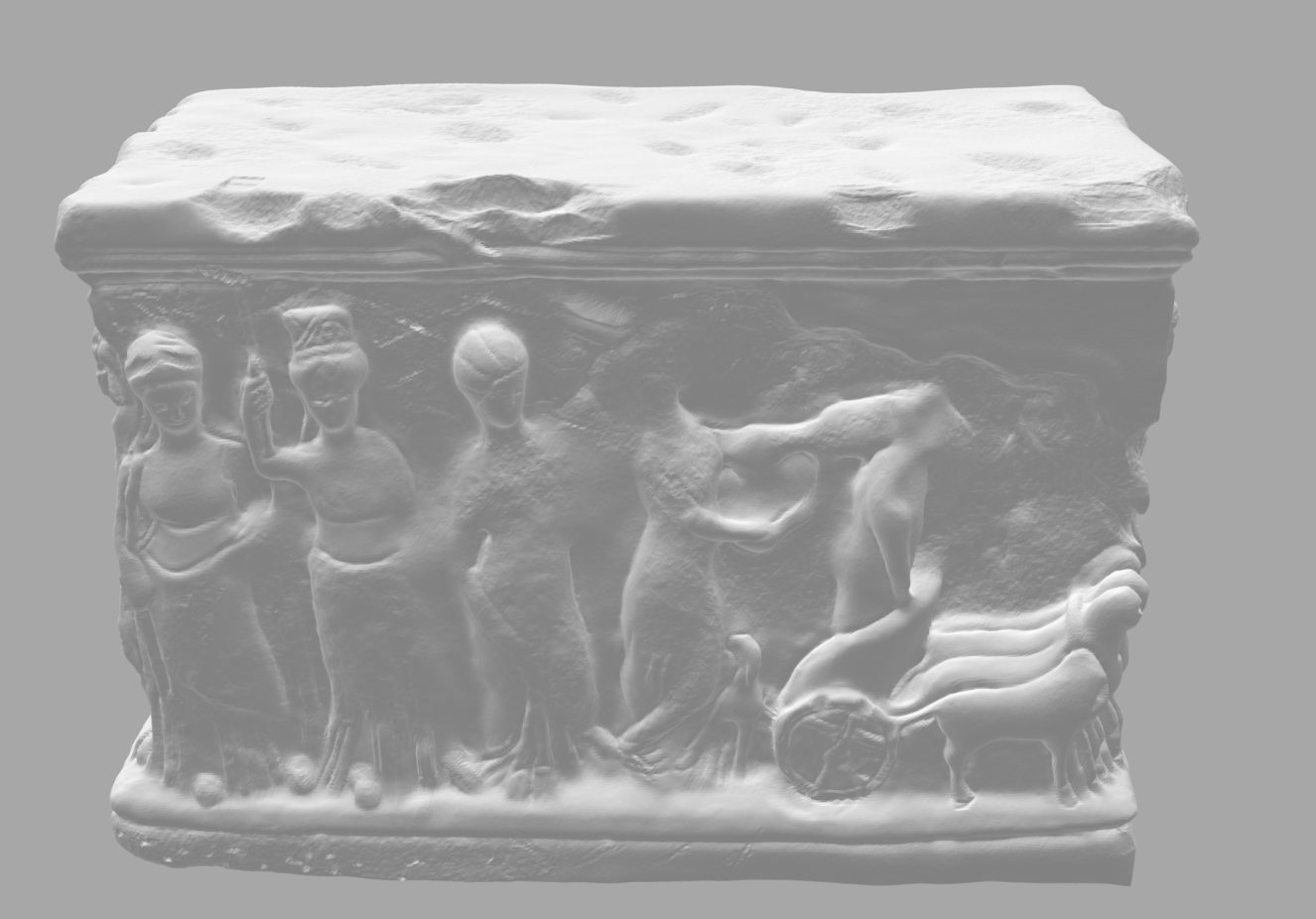
The reliefs on our small altar on the right represent the rape (in the sense of abduction) of Persephone (also Kore), the daughter of Zeus and Demeter, goddess of spring.
She was abducted by Hades, which caused her Mother to prevent all plants from growing because of her despair. To prevent the end of the world, an agreement was made and Kore spent half of the year with her mother, while Persephone ruled the underworld during the other half of the year with Hades.
The time she spends with her mother was the summer and the time she spend in the underworld the winter.
As she is the goddess of spring, she can be seen as a symbol for the feeling of hope and regeneration that comes with the spring.
Science as an inspiration
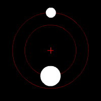
The glass spheres are inspired by the orbit of planets.
Creation
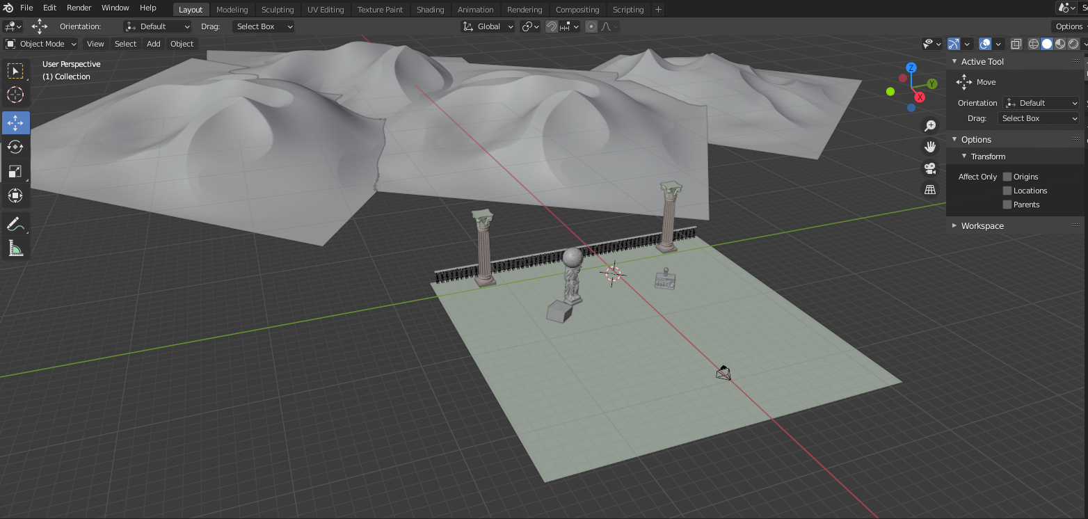
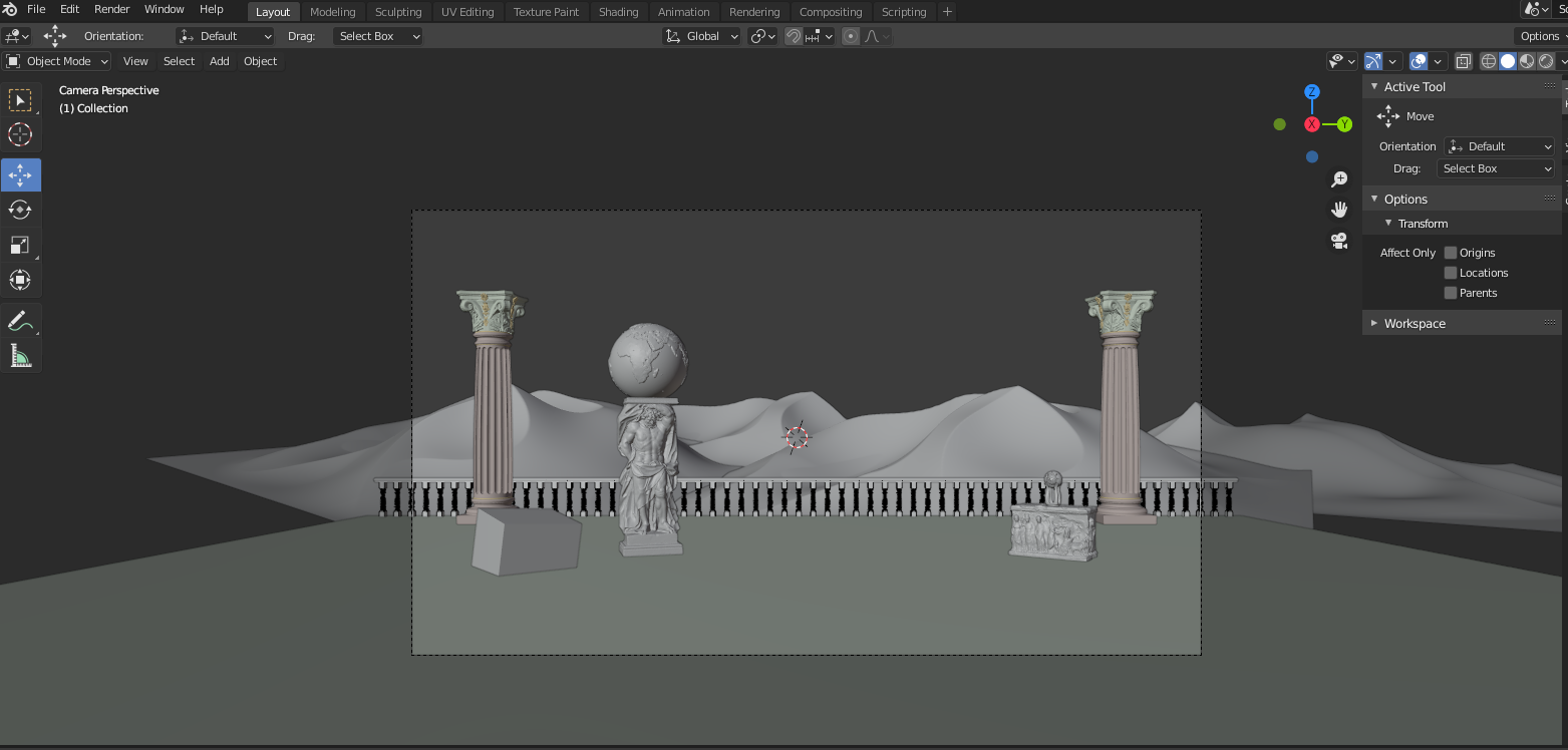
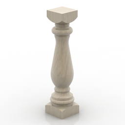
The main part of our model was created in Blender. The Atlas statue, the globe, the stone altar, the two parts of the golden sculpture, the pillar and the bar of the railing are third-party models, check the references for details. We rescaled and arranged them in Blender to fit our scene.
The Sphere and the stand of the golden sculpture on the right were two separate models that we combined.
The railing except the bars and the desert were created by us in Blender, while the glass spheres and the bloom were generated by our code.
Implementation
Bloom
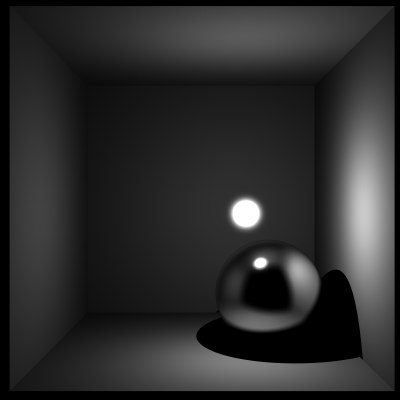
To create good looking representations of physical light sources we implemented a post processing bloom effect. We also added the ability for solids to ignore shadow rays, this makes it possible to place light sources in solids.
The implementation of bloom is located in ../rt/renderer.cpp and was implemented by Henry Janson.
Step 1:
Rendering the image

Step 2:
Selecting all the pixels that are over the luminosity threshold
Step 3:
Gaussian Blur in x direction
Step 4:
Gaussian Blur in y direction
Step 5:
Adding the rendering and the blur image together
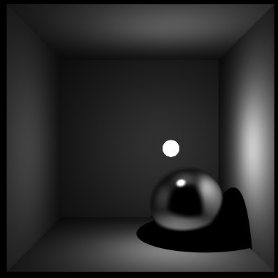
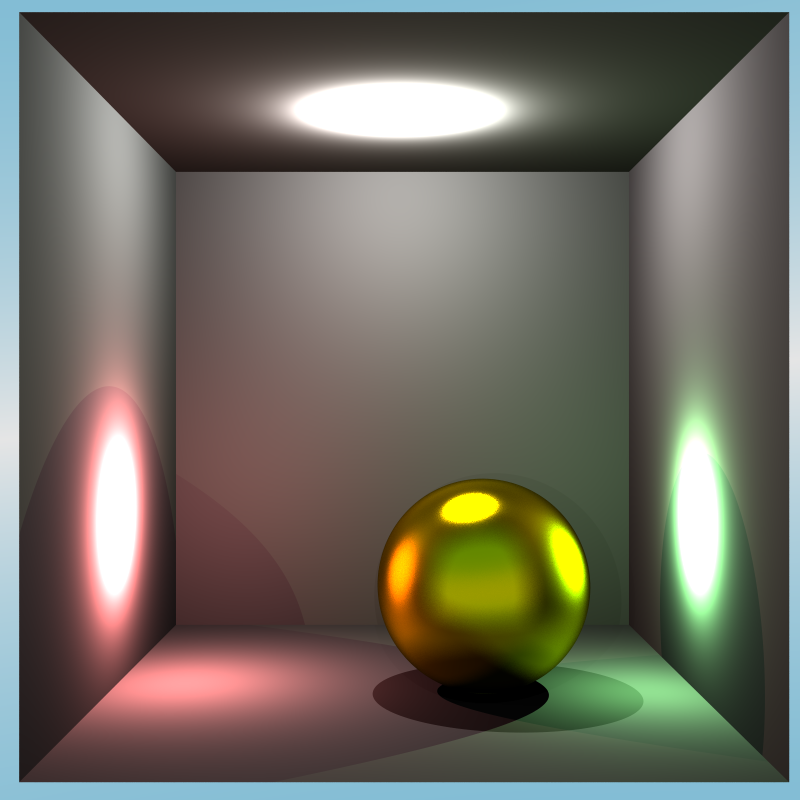
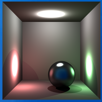
Extension of Fuzzy Mirror

The idea behind a fuzzy mirror is to allow a random deviation from the perfect reflection in a fixed specified range, to make the mirror look fuzzy. We extended the fuzzy mirror to model metals, by adding color to the mirror, and varying the range of allowed deviation for every point. For further details click below.
The implementation of fuzzymirrorextended.h is located in ../rt/materials/ and was implemented by Hendrik Suhr.
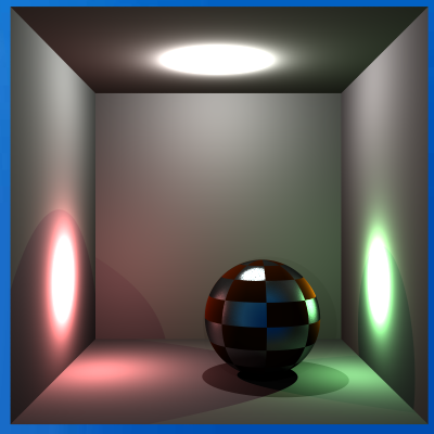
The first step on the road to model metal was simply adding an additional texture for the color.
Then we added yet another texture to scale the deviation interval individually for every point.This distribution texture scales the maximum deviation angle for every point, so white means full deviation allowed, black means perfect reflection.
On the picture on the left you can see this principle with a checkerboard texture.

And this is our final result, using perlin noise as the distribution texture.
Extension of Combined Materials
To be able to model rusty metal we added a new combined material, that does not merge the materials at every point, with a certain fixed weighting, but combines them with a distribution texture. For further details click below.
The implementation of combine2.0.h is located in ../rt/materials/ and was implemented by Hendrik Suhr.
After Extending Fuzzy Mirror, we were able to model metal, so to model the rust we just extended combined materials with the same principle, by adding an additional texture to specify the material for each point.
Here you can again see this principle with the good old checkerboard texture.
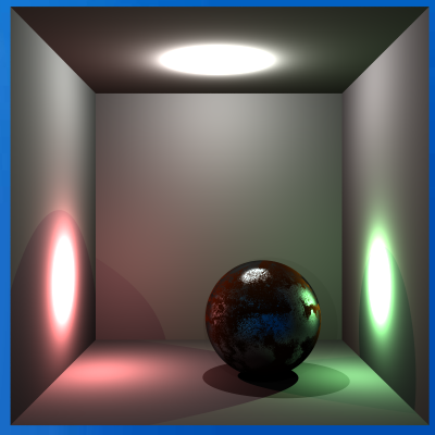
And here you can see the beautiful final result with a proper blotchy distribution texture.
Depth Of Field
To create a more realistic camera model we implemented a depth of field camera. This creates a better feel for depth in an image by blurring things that are far or close and only having the main subject of the image in focus.
The implementation of ../rt/cameras/dofperspective.h is located in /rt/cameras/ and was implemented by Henry Janson.
Level 1
aperture radius = 0
(no blurring)
Level 2
aperture radius = 0.1
Level 3
aperture radius = 0.2
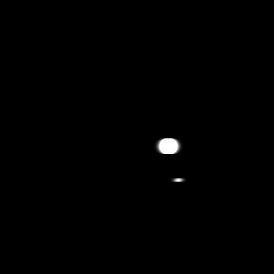
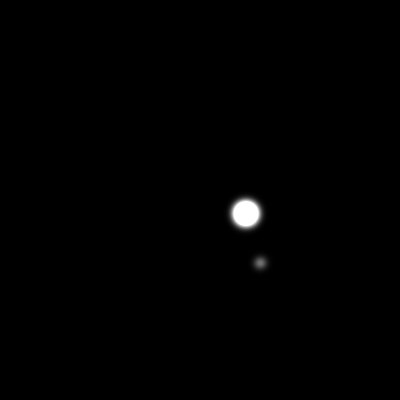
Sunlight
To illuminate such a large scene uniformly we implemented a new light source modeling sunlight. The sunlight acts like a point light that has the same relative position from every point it hits. We also added an environment light to approximate indirect illumination.
The implementation of ../rt/lights/sun.h is located in ../rt/lights/ and was implemented by Henry Janson.
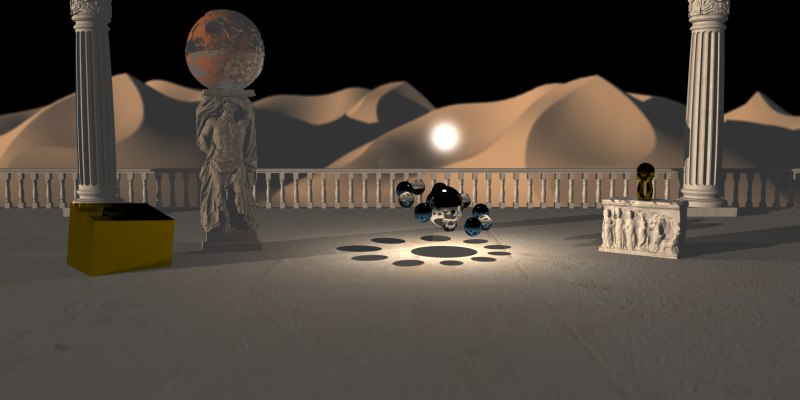
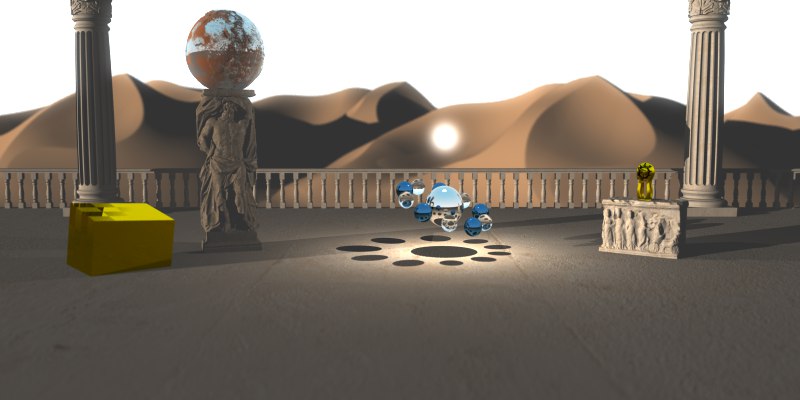
The scene without sunlight and without environment light.
The scene with sunlight, but without environment light.
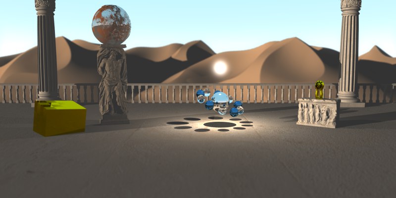
The scene with sunlight and environment light.
Environment Mapping
Inspired by a submission for the rendering competition of the past year (you can check it out here), we used the dot product between the up vector and the ray direction vector, to interpolate between white and light blue instead of just using an image texture or a constant color.
We first tried simple linear interpolation but we were not satisfied with the result yet, so we decided to add some none-linearity by taking the dot product to the power of 4 instead of just using the value itself.
The implementation of the environment mapping is distributed among several files:
Solid: ..\rt\solids\environment.h
Mapping: ..\rt\coordmappers\envmapper.h
Interpolation: ..\rt\materials\flatmaterial2.0.h
and was implemented by Hendrik Suhr.
The scene without environment mapping.
(up * ray.d)
(up * ray.d)4
Benchmark
Stats about our Scene
| Objects | Triangle Count |
|---|---|
| Columns | 117.972 * 2 Triangles |
| Sphere | 747.493 Triangles |
| Sculpture | 241.664 Triangles |
| Altar | 1.252.224 Triangles |
| Statue | 2.201.554 Triangles |
| Baluster | 835.320 Triangles |
| Globe | 737.280 Triangles |
| Dune | 2.088.968 Triangles |
| Cube | 10 Triangles |
| Ground | 2 Triangles + 1 InfinitePlane |
| Orbit | 11 Spheres |
| Environment: | 1 Environment Solid |
| Total | 8.340.459 Triangles + 11 Spheres + 1 InfinitePlane +1 Environment Solid |
Algorithms / Speed Up Techniques used
To be able to render such a complex scene we used multi-threading and SAH heuristic for the building of the BVH.
Rendering of our Scene
| Resolution | 4000 ✕ 2000 |
| BVH Build Time | 565s |
| Image Render Time | 16253s |
| Samples per pixel | 1.000 |
| Overall Samples | 8.000.000.000 |
| computing power of hardware | AMD Ryzen 1700 with 16GB RAM |
References
The third-party models we used:
The third-party textures we used:
The third-party images we used on our website:
Inspiration for our website layout:
The layout of the header of our website and the font-style is inpired by this free template, however we modified almost everything and created the main part of our site on our own.