Abstract
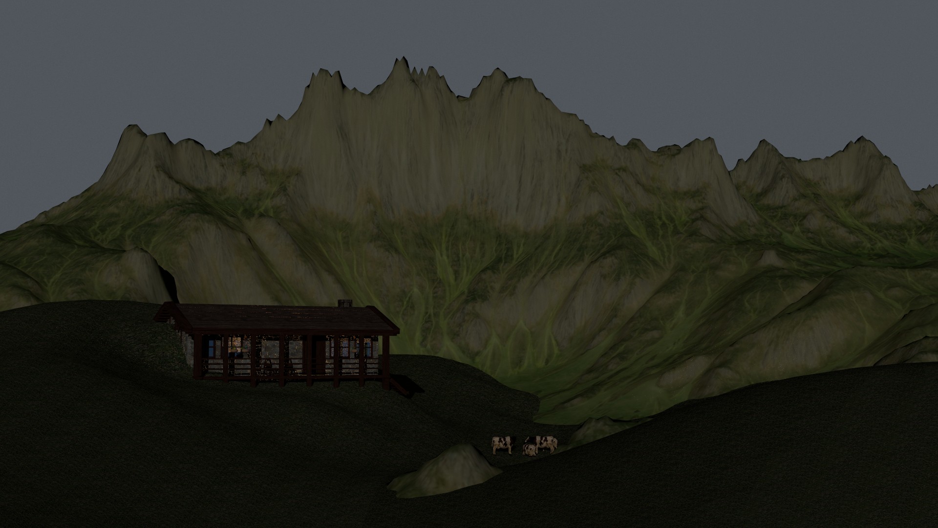
Our intention behind designing this image was for the viewer to experience the beauty of simplicity in nature by
imagining how it would feel to live in a log cabin in the alps among animals and nature.
Render Details
- Resolution: 1920 x 1080
- Render Time: 1423.14 seconds
-
Hardware:
Intel(R) Core(TM) i9-13900H CPU / NVIDIA GeForce RTX 4060 Laptop GPU / RAM: 32GB
Early Concepts
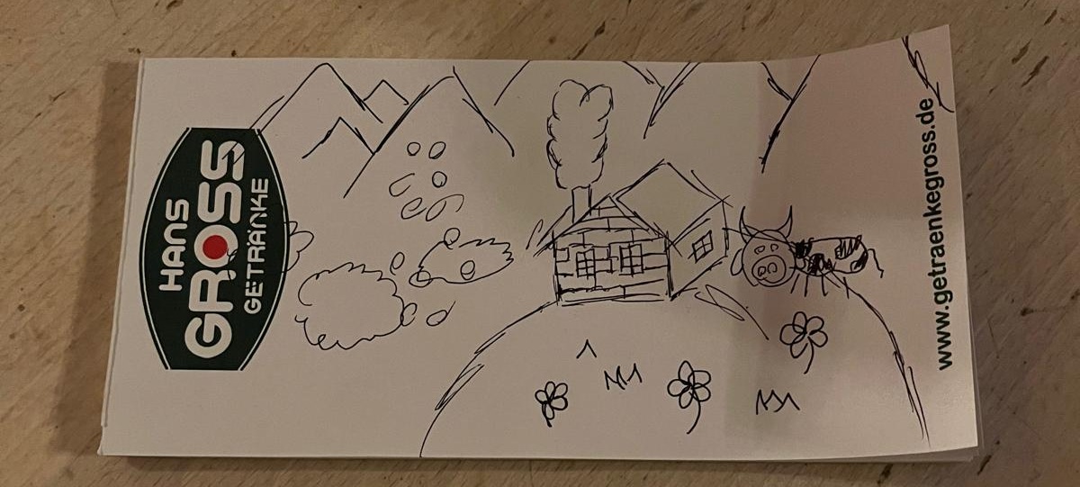
Our scene was initially inspired by the winter in the Swiss mountains, and after discussing a few ideas we had, we ended up with a masterfully crafted piece of art (shown below), which we have used as a guide when using blender to build it.
Intermediate Renders
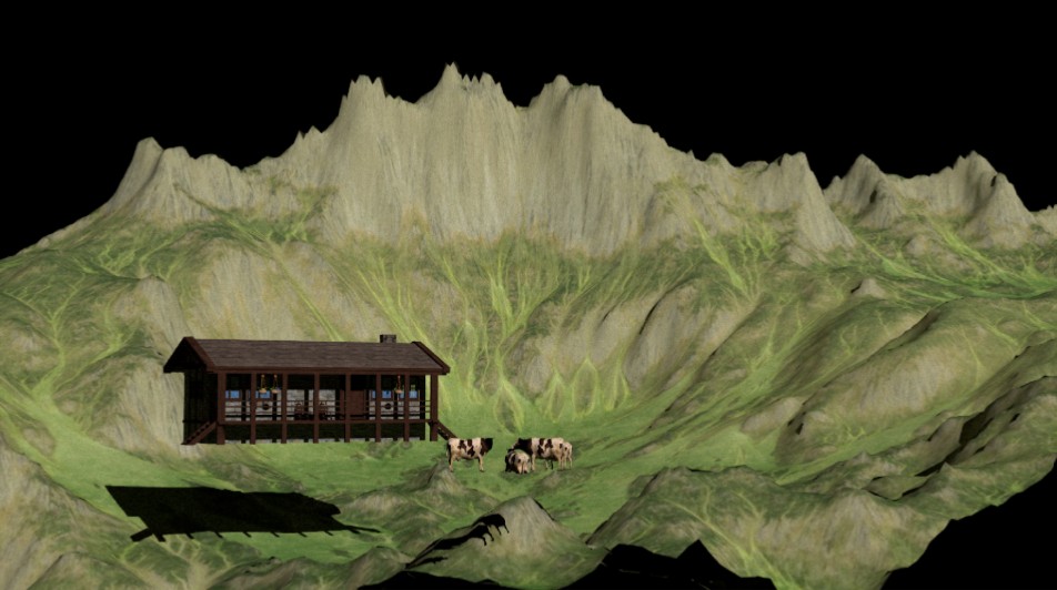
After this, we had a pretty good idea of what we wanted to render so we produced this simplified version with just some
assets in order to visualize how it would look.
Variations
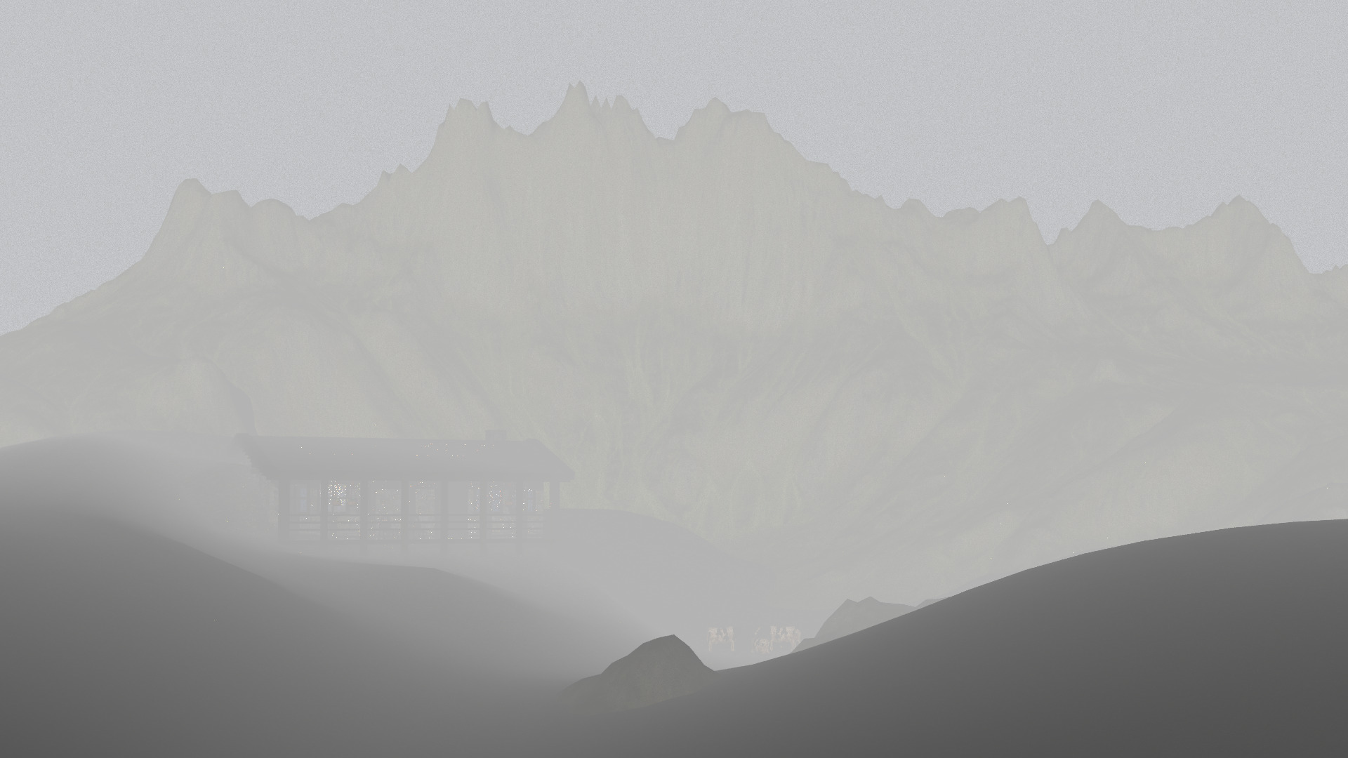
Another variation of the final scene that was also tried was the same scene but using fog postprocessing, which we found
a bit excessive:
B. Alpha Masking
Description:
Alpha masking simulates complex structures, such as leaves and plants, without relying on complex meshes. It does this
by sampling an image texture and discarding the intersection based on the probability generated from the sample.
Render Examples:
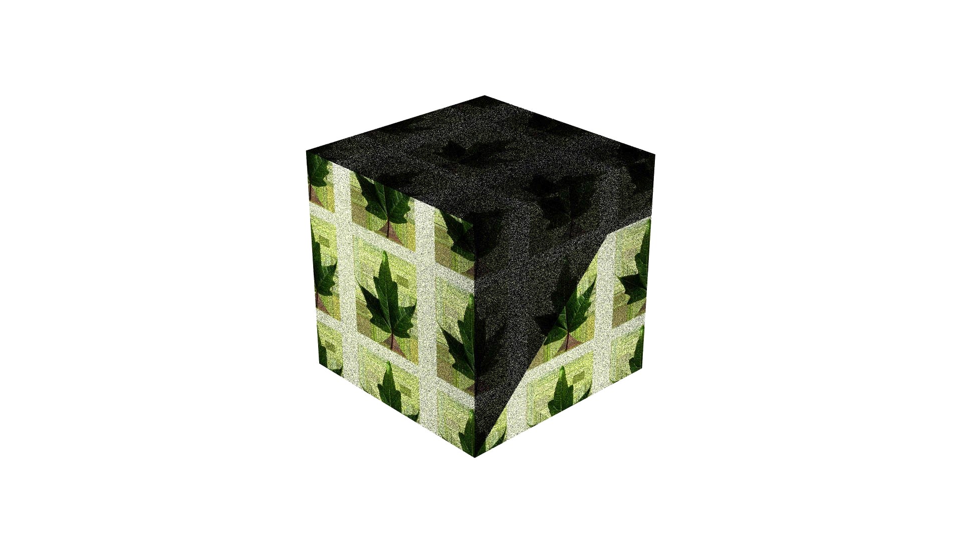
Without alpha masking (left), the pathtracer treats the cube as almost fully opaque and assumes geometry is present everywhere, leading to unwanted shadows and green reflections where we want the surface to appear transparent.
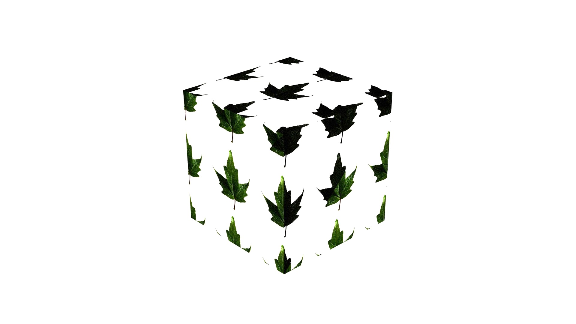
With alpha masking (right), the intersections on the cube are discarded based on the alpha texture. In parts between the leaves,
the sampled alpha value is close to 0, making intersections very likely to be rejected. This effectively simulates as if
the geometry in those areas is not there, leaving us with the desired leaf cutouts
Implementation:
Instance.hpp: Can now optionally read the alpha masking texture assigned to a shape.
instance.cpp: If there is an intersection, check whether alpha masking is present. If it is, generate an alpha value by
sampling the image texture at the intersection and convert it to a probability for dismissing the intersection. Then
generate a random number between 0 and 1. If the value is greater than the alpha value, dismiss the intersection.
Biggest Challenge:
The biggest challenge we faced when implementing this feature was understanding how a sampled texture value can be
interpreted as a probability for discarding ray-surface intersections. Although the alpha map is represented as a color
image, it is created as a grayscale texture and is guaranteed to be normalized and contain values in the range of 0-1.
This allows the sampled value to be treated as a probability and compared against a uniform random number to decide
whether an intersection should be discarded or not.
D. Post Processing (Fog Simulation)
Description:
This feature is used to simulate fog in the scene without expensive computations, simply by relying on a mathematical function that depends on depth of objects in the scene.
Render Examples:
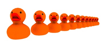
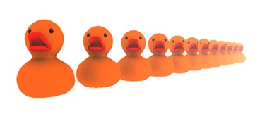
To the left, the basic scene without postprocessing, and to the right, the image with said effect applied.
Implementation:
For this feature to work, we added a new variable to the existing AOV integrator (depth), which takes the intersection distance and produces a depth map of the image, where each pixel has a color that stores the depth information.
We also added a new fog postprocessor that takes the original color output (i.e. the output of a direct integrator over the scene) and the output of running the AOV integrator with variables set to “depth”. These two are combined to produce the depth-based fog effect shown above.
Biggest Challenge:
The hardest part about this was actually figuring out with what structure the postprocessor should be implemented, because the depth information is only available at the integrators, not the postprocessors, so our initial version used a new integrator that combined fog and color directly (which is not pure postprocessing so we had to discard it), and
led up to the current version, whose structure is quite easier to understand (having a postprocessor do postprocessing instead of an integrator).
E. Normal Mapping
Description:
Normal mapping simulates small surface details, such as bumps or grooves, without the addition of extra geometry.
Instead, it samples a normal from a texture image and uses it as the shading normal, which affects how light reflects
and scatters across the surface.
Render Examples:
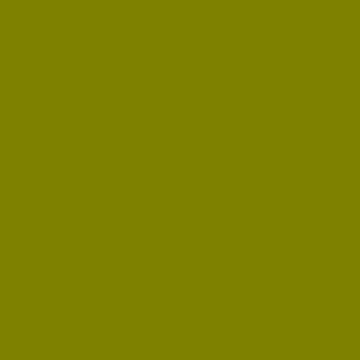
Without normal mapping (left), the surface normals are taken directly from the scene's geometry. Since the wall is flat, all
the normals are identical, which causes the lighting to be the same across the whole image.
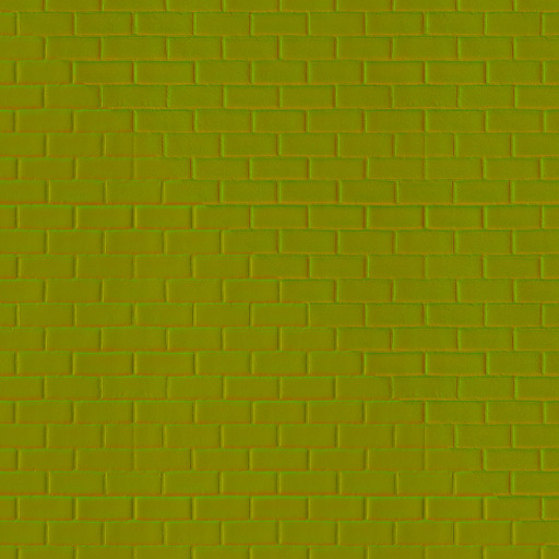
With normal mapping (right), sampled vectors from the normal map are transformed into world space and used for shading. This
introduces variation in the shading normals without modifying the underlying geometry, allowing the lighting to respond
as if the surface had much finer detail than it does.
Implementation:
instance.hpp: Can now optionally read the normal map texture assigned to a shape.
instance.cpp: Checks whether a normal map is present. If it is, sample the normal map texture at the intersection,
transform the sampled normal to world space, and set it as the new shading normal.
Biggest Challenge:
The biggest challenge we faced when implementing this feature was understanding how to correctly transform the sampled
vector from normal space to world space. This requires constructing a tangent-bitangent-normal(TBN) matrix and using it
as a change-of-basis to perform the conversion. Thankfully, OpenGL has a very extensive article that talks about this
exact challenge.
M.1. Basic Area Light Sampling
Description:
This feature consists of implementing a new kind of lighting called area lights. An area light is an emissive shape that
acts as a light source with non-zero size. By explicitly sampling random points on its surface for direct illumination,
we can achieve the same lighting result with significantly less variance than with the other kinds of lighting that are
supported by the renderer.
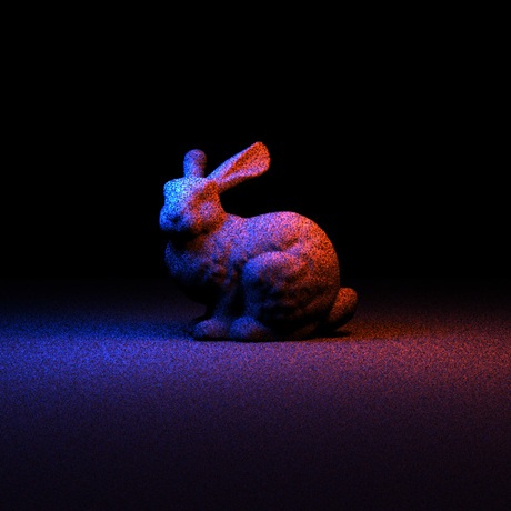
Render Examples:
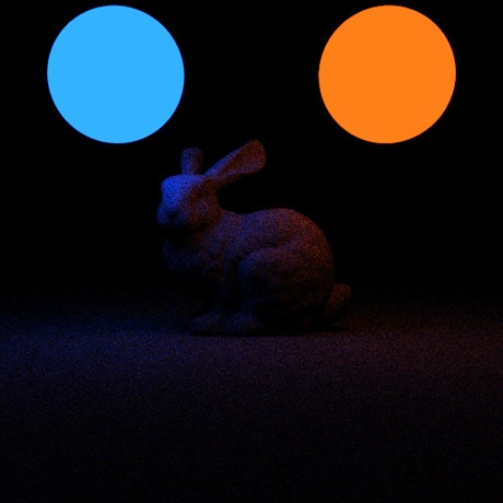
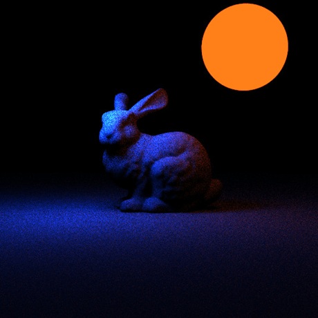
In the following renders, lambertian emissive surfaces are used as a placeholder for where area lights will be. Area lights are not visible as per the specification.
From left to right, no area lights (2 lambertian emissive surfaces), one area light (and 1 lambertian emissive surface), and two area lights.
Implementation:
For this feature to work, we had to modify the code for the direct integrator's Li method, so that the variables result
and indirect only added contribution from non-area lights (so that area lights' contribution is not counted twice).
We also created a new AreaLight class that implements the sampleDirect method of the Light class and implements a
version of the canBeIntersected method that returns true.
We also modified the Sphere class in order to implement its sampleArea method.
Biggest Challenge:
The biggest challenge faced when implementing this feature was figuring out in what way we could check if a given light
source was an area light or not in the Li method of the direct integrator in order to decide if its contribution should
be added or not. After thinking about many ways to do this we noticed the method that every Light subclass implements
canBeIntersected, which can be used effectively as an indicator of what lights are area lights and which ones aren't.
M.2. Improved Area Light Sampling
Description:
In basic area light sampling, points on the area light are randomly sampled, no matter their contribution to the final
image. For this feature, we focused on improving area light sampling for sphere shapes.
This feature consists of obtaining the cone that bounds the part of the sphere that is visible from the origin point,
and only sampling points from this part of the sphere in order to obtain a much smoother result than what would be
obtained with basic area light sampling.
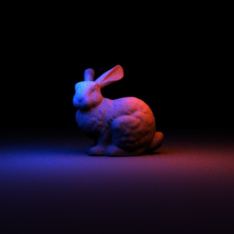
Render Examples:
The following scene is the same as the one used for basic area light sampling, but this time with improved area light sampling. It can be seen that this render is a lot less grainy and smoother than the image from the basic render above.
Implementation:
For this feature to work we had to modify the AreaLight class that was added for the basic area light sampling. In this
class, we added a new method that produces samples based on the reasoning described in this feature's description.
In this class, we also added a new property that is in charge of calling this improved sampling routine if the flag
useImprovedSampling is set to true in the xml, otherwise it will render using basic area lighting.
Biggest Challenge:
The biggest challenge faced when implementing this feature was to figure out in which coordinate system the “wi” vector
was, as the render being produced at the start had a lavender tone, which is not the color of the area lights and after
debugging for a long time, we found out that the “wi” vector was in a local coordinate system with respect to the solid
angle cone, and we had forgotten to transform it into world coordinates, after doing which it worked perfectly.